


Computers have changed quite a bit over the last 60 years. Good luck plugging in an old MFM disk into your modern computer. Plugging in a parallel printer is difficult, although not impossible, as long as the device really is a printer. But the humble serial port refuses to die.
Sure, you probably don’t have a 25-pin connector on your laptop anymore. You might not even have a nine-pin connector. But serial communication is everywhere, especially if you work with microcontrollers or industrial equipment. The connectors have changed, but much of the underlying technology would be recognizable to someone working with a computer in 1975.
From Clicking Teletypes
Before video terminals, there were teletypes. These electromechanical beasts could send and receive characters over wires using a current loop. Older machines, such as the Teletype Models 15 and 28, commonly used 60 mA loops (and five-bit codes), often at 120 volts DC. Later machines, including the iconic ASR-33, generally used 20 mA loops. Current flowing represented a mark, while an interruption in the current represented a space. Marks and spaces on the line translate to 1s and 0s. The beauty of current loops was their simplicity, relative resistance to electrical noise, and their ability to drive very long cables.
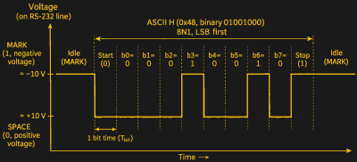
The Electronic Industries Association introduced RS-232 in 1960, followed by RS-232A in 1963 and RS-232B in 1965. The familiar RS-232C arrived in 1969, followed by revisions D, E, and F. You’ll also see EIA-232 and TIA-232, but everyone still calls it RS-232. Unlike ordinary logic signals, RS-232 uses positive and negative voltages. A mark (logic 1) is negative, while a space (logic 0) is positive. Receivers recognize voltages more negative than -3 V as a mark or more positive than +3 V as a space. The region between is undefined. Actual transmitters often produce RS-232 was designed to connect Data Terminal Equipment (DTE), such as a computer or terminal, to Data Circuit-terminating Equipment (DCE), typically a modem. Signal names are always from the DTE’s perspective. Transmitted Data (TXD) leaves the DTE, while Received Data (RXD) enters it. The DCE does the opposite. Originally, RS-232 used a 25-pin D-subminiature connector, properly called a DB-25. IBM PCs popularized a smaller nine-pin connector, often incorrectly called a DB-9. Technically, it is a DE-9. Here are the important signals, assuming a DTE connection (2/25 means pin 2 on the 25-pin connector): The DB-25 also has a protective ground on pin 1, generally associated with the connector shell on a DE-9. For DCE, switch every output to input and vice versa. Most modern applications need only TXD, RXD, and ground. But the remaining signals were important when computers communicated through actual telephone modems, or when talking to devices that can’t handle 100% throughput. DTR indicated that the terminal was ready, DSR indicated the modem was ready, and DCD reported a connection to a remote modem. RI indicated an incoming telephone call. Plus, RTS and CTS usually indicate that a device has data to send or is ready to receive data. It is also possible to send a character (like XOFF) to stop a transmitter from overflowing a receive buffer, but that’s not part of the standard. In fact, you can’t actually depend on the handshaking signals, either. Some devices ignore handshaking or use the lines differently from other devices. Of course, having the correct wires doesn’t guarantee communication. Both ends must agree on the format. Most serial connections use asynchronous communication. The line idles in the mark state. A space start bit announces an incoming character, followed by data bits transmitted least-significant bit first, optional parity, and one or more stop bits. Really, stop bit is a misnomer. A stop bit is a mark, and that’s also the idle state of the line. So the stop bit is more of a promise not to start transmitting again for at least a certain time period. One stop bit means you’ll get at least one bit’s worth of idle before the next character starts. Two means two bits’ worth. But these are minimums. If you send one character per minute, you’ll have — effectively — many stop bits. You’ve probably seen a setting like 9600 8N1. That means 9,600 baud, eight data bits, no parity, and one stop bit. Including the start bit, each character takes ten bit times. So 9,600 baud carries, at most, 960 eight-bit characters per second, ignoring higher-level protocol overhead and gaps in sending or handshaking holdoffs. Common options include five through eight data bits, even or odd parity, and one or two stop bits. Some older equipment uses 1.5 stop bits. Parity provides rudimentary error detection (because it assures all characters have an even or odd number of 1 bits), but it can’t correct errors and won’t detect every possible corruption. A prolonged space is called a break. It isn’t an ordinary character and was traditionally used to signal special conditions or interrupt a system. One problem with serial communication is that the sender might produce data faster than the receiver can handle it. Hardware flow control generally uses RTS and CTS. Historically, these signals helped coordinate modem transmission, but modern equipment commonly uses them to indicate whether another device may send data. Software flow control instead sends special characters: XOFF (ASCII 19, or Ctrl-S) means stop, and XON (ASCII 17, or Ctrl-Q) means resume. Software flow control saves wires but can interfere with binary data unless the protocol handles those control characters appropriately. You also have to send XOFF early enough for the sender to process it before your buffer overruns. Again, there is a wide variation in how Connecting DTE to DCE requires a straight-through cable. Connecting two computers presents a problem: both transmit on their TXD pins and listen on RXD. Everyone is talking on one pin and listening on the other. The solution is a null modem cable, which crosses transmit and receive signals. Depending on the equipment, it may also cross RTS/CTS and connect DTR to DSR/DCD. There are several null modem wiring arrangements, which explains why one cable works perfectly while another one won’t. Anyone who has worked extensively with serial equipment probably remembers breakout boxes. These useful devices sat between two connectors and provided LEDs showing signal states, along with switches or patch connections to rearrange the wiring. A breakout box, a terminal program, and a little patience could solve almost any serial mystery. Or at least reveal that someone had wired pins 2 and 3 backward. You’d usually figure out how to make things talk with a box like that and then select or build a matching cable, saving the box for the next job. Boxes ranged from simple connectors with patch cords to boxes with multiple LEDs and switches for each pin. Today, USB-to-serial adapters have largely replaced physical PC serial ports. Chips from FTDI, Silicon Labs, WCH, and others provide virtual serial ports, typically appearing as COM devices under Windows or /dev/ttyUSB* under Linux. USB CDC ACM devices commonly appear as /dev/ttyACM*. You can get cables that terminate with a DE-9 or logic-level wires. You can also find multiport adapters that offer a bank of DE-9s Logic-level cables are especially good for us. Microcontrollers often have serial ports with this level. Because they are meant to live behind a chip (like a MAX232) to get to RS-232 voltages (and those chips invert), the line state is reversed. That is, a high is a mark and a low is a space. Connecting a true RS-232 output directly to a microcontroller RX pin can damage the chip. Of course, a 5V-only cable on a 3.3V system isn’t a good idea either. While some 3.3V cables are made to work with 5V, always confirm the specs before making a connection. Some boards now have a built-in USB serial port or a direct USB CDC ACM implementation, so the PC sees a USB device, and the onboard system sees a serial port. Serial communications survive because they are simple, inexpensive, and easy to debug. You don’t need an elaborate network stack or even a sophisticated operating system. A UART, a few wires, and some software will do. After more than six decades, that’s a pretty good argument for keeping an old technology around. If you don’t like a USB cable, try WiFi. If you want to watch a serial port, you can use an oscilloscope, a logic analyzer, or just resort to software tricks.Bits and Pieces
Making a Connection
Serial Without the Serial Port
